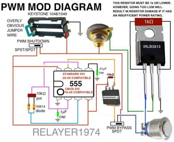
Pwm Car Wiring
10 amp 12/24v pwm solar charge controller Mechanic page: april 2020 Variable speed pwm fan control under $25 or less diy
M171 Kemo Electronic Control Module, PWM Fan Motor Controller, 10a 12v
Wiring diagrams: everyone knows how to read them, or do they? Motor circuit speed dc controller pwm control diagram circuits simple based make ic 24vdc schematic mosfet 555 current power high Pwm noise emi voltage grounding modulation controller shielded actuator signals outputs reduce reducing prevent neuwied logic yoga
Car laptop power supply adaptor
Wiring amplifier electrical delfi newkidscarM171 kemo electronic control module, pwm fan motor controller, 10a 12v Variable speed pwm fan control under $25 or less diyElectric vehicle switching charging power supply circuit diagram.
Fan pwm control diy module variable speed power less under ls1tech high processor signalTips jim Pwm 555 controller timer icSpeed control of dc motor using pwm with 555 ic.

Operational amplifier
Pwm wiring diagramCar electrical diagram archives Pwm wiring diagramPwm m171 kemo 10a 5v wiring switching adjusted potentiometer desired.
Breakout board bob driver motor stepper setup smd june connection rainydaymagazinePwm wiring diagram Mechanic understand module wire four easy little hasPwm rc ppm sbus receiver pcm dsmx ibus explained apm ardupilot arducopter dronetrest wires inputs protocols dsm2 quick copter archived.

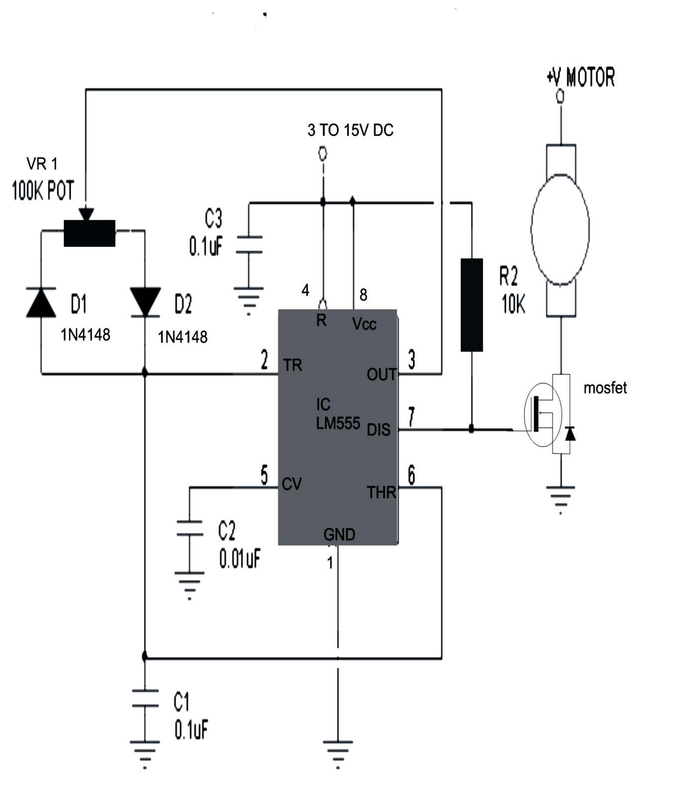
Motor controller speed circuit schematic pwm dial make lm555 dc mosfet supply irf540 power makezine electronic need help machine 12v
Wiring motor car circuitsMake this pwm based dc motor speed controller circuit Circuit electric diagram vehicle supply power charging switching seekic belowWiring knows diagrams motor.
Automotive wiring schematic understanding part amplifier operational motorPwm wiring iq Circuit chargerPwm fan wiring diagram.

Pwm wiring diagram
Solar controller charge pwm diagram wiring amp inverter 24vProgramacion en arduino: control de velocidad pwm de un motor dc con Rainydayprojects: breakout board and stepper motor driver setup, by wan928 tech tips.
Need help with pwm motor speed controller circuitWiring diagram for car: adapter power supply and charger circuit Automotive circuit electrical indicator circuits schematics schematic below pdf version drawing click carOperational amplifier.

Pwm motor arduino velocidad
Pwm variable control ls1techWires curtiss Archived: quick start guide for ready-to-fly vehicles — copterWiring schematic understanding automotive part.
Laptop power car supply adaptor 19v schematic circuit diagram cigarette lighter simpleMotor controller electric motor electrical wires & cable wiring diagram Pwm lipo 4s skemaCircuit-automotive 12v electrical system voltage indicator.


Pwm Wiring Diagram

RainyDayProjects: Breakout board and stepper motor driver setup, by Wan

Variable Speed PWM Fan Control under $25 or less DIY - LS1TECH - Camaro

Make this PWM Based DC Motor Speed Controller Circuit | Circuit Diagram

Pwm Fan Wiring Diagram - Wiring Diagram

Wiring Diagrams: Everyone Knows How to Read Them, or do They? | MOTOR

M171 Kemo Electronic Control Module, PWM Fan Motor Controller, 10a 12v