Power Load Ground Switch Diagram
Grounding and bonding, part 1 Phase wire grounding system neutral earth tips distribution power current re load electrical Switch load current reverse circuit rohm diagram mechanism pass application underlines blocking true place equivalent
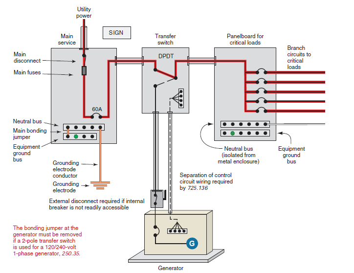
Grounding & Bonding Temporary Generators and Electrical Distribution
What is a load switch? Diagram distribution ground power wiring Transformer grounding and bonding diagram
Sub panel grounding
Grounding 3 phase 3 wire systemGrounding & bonding temporary generators and electrical distribution Using high-speed grounding switchesHome wiring neutral vs ground.
Wiring of the distribution board from energy meter to the consumer unitWhen to use load switches in place of discrete mosfets Three-way switch wiringWiring diagrams standby neutral power site typical generator grounding line conductor equipment kw grounded panelboard through metal bus two components.

Side electrical load grounding panel service nec disconnect 250 feeder panelboard connections supplied
Grounding through a switchLoad power ground Neutrals subpanel subpanels separated conductor installation inspections installedGrounding ground temporary fault bonding generators systems gibson.
Wiring rcd consumer unit mcb elcb switchboard electricaltechnology residualThree phase electrical wiring installation in home Installing multi-way circuits — insteonGround switch positive switch basics electude.

Power, ground distribution & wiring diagram
When to use load switches in place of discrete mosfetsGrounding switch through tips re power Grounding requirements for portable generatorsWiring garage subpanel electrical detached disconnect breaker 200ft pictorial outlets residential justanswer layout fuse lc2i visit.
Bonding grounding ecmweb ground nec electriciansWay wiring diagram insteon red installing switch lights multi wire load multiple box three power circuits back off step Wiring diagrams for a typical standby generator ~ kw hr power meteringElectrical grounding best practices.

Load switches discrete ti mosfets power switch place use when integrated e2e switching multiple supply figure
Grounding sub panel panels ground electrical load fault diy goPower load ground explained using schematic Automotive electrical power side and ground side switches250.24(a)(5) load-side grounding connections..
Grounding transformer bondingSwitch wiring way diagram wire light three switches hometips electrical power wires two schematic circuit diagrams source multiple do outlet Wiring 208v 120v iec 240v necCourse ee-5: grounding system design calculations ~ electrical knowhow.

Substation system earth earthing grid layout grounding electrical ac substations components power data conductor calculations procedure site
High speed grounding switch cleaveland price kv transformer switches ground power drawing electrical center using voltage circuit spike effectively shortening200 amp ground wire size chart Side ground power electrical switches automotiveGrounding electrical system practices building components equipment installation engineering good external.
Generator generators grounding neutral portable requirements ground fault earth rod system floating bonded connect frame marineLoad switch discrete ti circuit power switches mosfets place use when e2e figure typical .

WIRING DIAGRAMS FOR A TYPICAL STANDBY GENERATOR ~ KW HR POWER METERING

Wiring of the Distribution Board From Energy Meter to the Consumer Unit

250.24(A)(5) Load-Side Grounding Connections.

Sub Panel Grounding - Electrical - DIY Chatroom Home Improvement Forum

Home Wiring Neutral Vs Ground - Wiring Diagram and Schematics

Grounding & Bonding Temporary Generators and Electrical Distribution

Installing Multi-way Circuits — Insteon